 Lviv Radio Engineering Research
Institute (LRERI), Ukraine
Lviv Radio Engineering Research
Institute (LRERI), Ukraine
Lviv Radio Engineering Research
Institute (LRERI), Ukraine
Lviv Radio Engineering Research
Institute (LRERI), Ukraine
|
|
SE LRERI history and product list are here
(pdf, 3.8 Mb).
LRERI offers the line of state-of-the-art millimeter-wave radar systems and radar sensors covering a range of 36 GHz to 94 GHz suited to unique customer requirements.
LRERI’s products serve a range of applications in military, industrial and research markets.
LRERI’s products encompass three types of technologies, namely waveguide, planar, and microelectronic.1. 3 mm Pulse Collision Avoidance Radar (CAR)
2. Millimeter Wave Radar Sensor for Maintaining the Distance (RSMD)
3. Millimeter Wave Ballistic Station (MWBS)
4. Millimeter Radar Instrument for Measurement of Land Vehicle Movement Parameters (RIMMP)
5. ARMOURED VEHICLES BASED COMAND and CONTROL SYSTEMS (TIUS)
Applications
CAR has worked out for collision avoidance tackling safety problems for small height flights of helicopters and light planes in mountain areas, in urban and industrial building areas, over agriculture lands having high voltage transmission lines.
Description
The radar is compared to a well-known similar one called ROMEO which was developed by Thomson Company (France), has considerably smaller (2.5 times) dimension and weight. This ensures simple compact installation and application of the system on super light helicopters. Along with this high resolving ability of the radar for angular data and for operating distance counts for high quality of radio location picture being very close to television.
Radar function of collision prevention is fulfilled any time of day and night, all weather conditions and under any environment (dusty, smoky), low-power emission used in radar system allows environment-friendly operation, electromagnetic compatibility, security, and noise stability.
Compact scan 3 mm radar is a completely solid-state pulse radar fast electromechanically scanning the antenna pattern of a large angle sector. The radar system was developed using highly advanced technologies in the field of SHF engineering and analog and digital signal processing devices.
The radar consists of two completed units: antenna head and signal processing and controlling unit and operates along with established helicopter devices; the terminal and gyroscope detectors.
Antenna head is composed of antenna system; devices scanning antenna pattern for azimuthal angle and area with corresponding detectors of twist-reflector position angle antenna-scan motor; antenna head stabilization device for roll with position detector and antenna-scan motor; radio transparent radome; receiving-transmitting device; and video frequency receiver. The antenna system consists of diagram building parts (feed horn; twist-reflector; and transreflector). Receiving –transmitting device includes receiving-transmitting SHF module and power supply unit for receiving-transmitting SHF module.
Signal processing and controlling unit is a digital part of the radar. It is composed of antenna actuator electronics; video processing and synchronization unit; secondary power supply unit for signal processing and antenna head controlling unit.
Wide range of operating temperatures is ensured with the help of constructive and technological innovations used in receiver development. Thermostated driving avalanche auto generator, frequency stabilization which is conducted by highly qualitative capacitor, generates a sequence of radio pulses, that are fed to avalanche diode amplifier input. Thermostabilization characteristics of this amplifier are carried out in the process of temperature correction of supplied current of amplifier stages. This transmitting device scheme, being very simple, ensures high spectrum clearance of output signals and low thermal bias of the operating frequency. Tests proved, that operating frequency thermal bias does not exceed (–10...+10) MHz in –50…+50 temperature range.
Antenna actuator mechanism and antenna contain a series of constructive innovations. These innovations allowed us to implement fast scanning of antenna pattern and to provide high electrical features. The main complexity of the work completed on optimization of antenna unit appeared to be strict weight and dimensions requirements for the radar as a whole.
The radar also has built-in test control for operational availability and improved test control from external computer.
Scanning region:
for distance …………… 20 . . . 2500 m;
short-range region …….. 20 . . . 1500 m;
long-range region …... 1000 . . . 2500 m;
for azimuthal angle ……120 degrees;
for area angle ………… up to 15 degrees;
referring to targetings on area angle (programmable in the range from 1 degree to 60 degrees with increment of degree).Scanning period (of radar picture update):
with the given scanning area dimensions:
120 degrees x1 degree (one azimuthal line)
65 . . . 70 msec;
120 degrees x30 degrees (30 azimuthal lines on area angle)
1.8 . . . 2.8 sec;Detection distance:
high voltage transmission line wires with the diameter of 10 mm not less than 600m;
objects with surface of effective scattering >30 square m up to 2500 m;Root-mean deviation:
from point target angle data not exceeding 0.5 degree;
angle range of targeting for area angle and roll given
- built-in or external detectors;Consumed power:
(with no terminal) …. About 80 Watts
supplied voltage …... 22 . . . 30 VDesign:
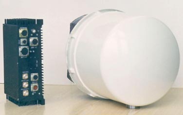
Antenna head
diameter ..................... 320 mm;
length ......................... 420 mm;
weight ........................ about 15 kg.Characteristics of constituents:
Antenna
polarization is linear horizontal or vertical;
gain in main lobe ............... 42-40dB;
sidelobes level lower main lobe ...... -23 dB;
antenna pattern beamwidth ........ 55' ... 65';
beam scanning velocity ........... up to 2000 deg/sec;
Transmitter
pulse with avalanche diode,
output power of a pulse is not less than 10 W,
pulse duration .............. 30 ... 100 nsec.
Receiver
super local oscillator with logarithmic
amplitude characteristic,
noise ratio .................... not exceeding 11 dB;
Processor
microcomputer ADSP 2181
FPGA Xilinx
two external exchange channels RS 232
RS 485 with exchange rate 38 115 kbot;
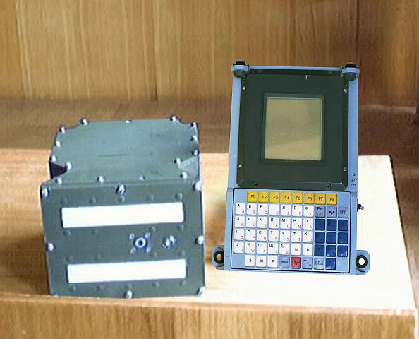
Terminal
PC based, type is defined by the installation site and customer requirements,
configuration:
similar to Pentium 166, RAM 15 Mb, hard disk 1 Gb, display 640x480 pic,
256 colours.
Purpose
RSMD is designed for maintaining the distance between the ground vehicles when the column moves in severe environmental conditions (rain, fog, snow, dust) in order to increase the speed of the column up to 40-50 Km/hr.
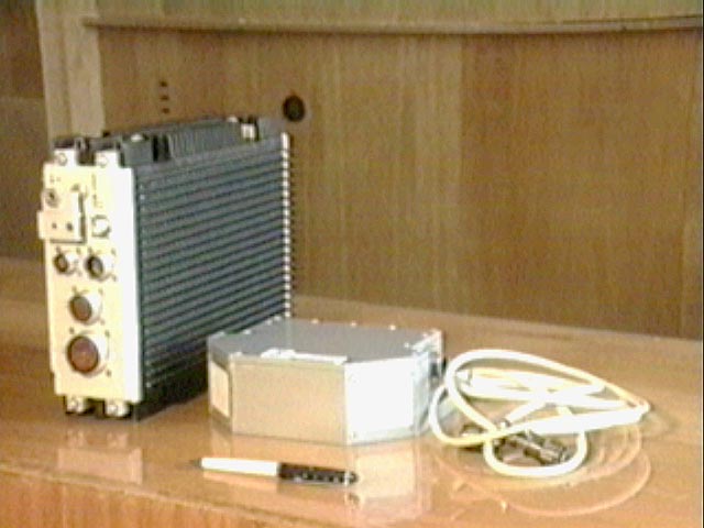
Description
RSMD measures the range to the vehicle moving in front and equipped with the RSMD and to the vehicle moving behind and not equipped with the RSMD and transmits commands from the vehicle moving in front to the vehicle moving behind under reduced optical visibility conditions and any time during 24 hours.
RSMD provides transmission from the vehicle moving in front and reception by the vehicle moving behind of up to 5 commands via a transponder radio channel.Complete Set
- Measurement unit …………………… 1 pc
- Transmit/receive unit with antennas … 3 pcsMain specifications: Range (R) to:
- vehicle equipped with RSMD facility ………………… 10 – 80 m;
- vehicle (obstacle) not equipped with RSMD facility …. 10 – 25 m;
Sector for measurement of range to:
a) vehicle equipped with RSMD facility:
- in horizontal plane …………………………. (-45...+45) degrees;
- in vertical plane ……………………………. (-10...+10) degrees;
b) vehicle (obstacle) not equipped with RSMD facility:
- in vertical plane ……………………………. (-10...+10) degrees;
- sector width in horizontal plane
at a distance of 10 m ………………………….. 4.0 – 6.0 m;
Maximum error of range measurement ……………... +(10%R+0.8) m;
Power supply (rated d.c. voltage) …………………. 27 V;
Total power consumption …………………………. 100 W;
Instrumentation volume:
- measurement unit …………………………….5 kube dm;
- transmit/receive unit with antennas ………. 1.7 kube dm.
LRERI offers the line of state-of-the-art Millimeter Wave Ballistic Stations (MWBS) are designed to measure the muzzle velocity, acceleration and barrel transit time of a wide variety of ammunition for field and tank artillery, naval and anti aircraft applications. Muzzle velocity measurement results are transmitted via the communications interface to the Fire Control System computer, accurate muzzle velocity data significantly increases the first round hit probability. MWBS provide extremely high security and interference immunity due to the usage of the portion millimetric waves with the maximum atmospheric attenuation.
|
|
|
|
|
| Measurands:
- muzzle velocity - acceleration - barrel transit time |
+ + + |
+ + + |
+ + + |
| Accuracy:
- muzzle velocity, % - acceleration, % - barrel transit time, msec when antenna elevation is not less than, deg |
0.2 3 10 |
0.1 1 0.4 |
0.1 1 0.7 |
| Muzzle Velocity Range, m/sec |
|
|
|
| Working Frequency Range |
|
||
| Caliber Range, mm |
|
|
|
| Firing Rate, rounds per minute |
|
|
|
| Supply voltage, V |
|
|
|
| Input power, w |
|
|
|
| Antenna Elevation Beamwidth, deg |
|
|
|
| Antenna Horizontal Beamwidth, deg |
|
|
|
| Reprogramming Capability at field level
for introducing new guns, projectiles |
|
|
|
| BIT |
|
|
|
| Printer |
|
|
|
| Modular design |
|
|
|
| Trigger |
|
|
|
| Corrosion protection |
|
|
|
| User menu |
|
|
|
| Controlled directly from FCS |
|
|
|
| Store the Muzzle Velocity Variation
information, combinations |
|
|
|
| Maximum Range as a function of
caliber, d, m R max = 104 (adb - c) |
b = 0.5 c = 0.06 |
b = 0.4 c = 0.01 |
b = 0.45 c = 0.01 |
| Dimensions, mm
- transmit/receive unit with antennas - processing unit |
290/224/123 |
290/224/123 |
LT 386SX/P |
| Weight, kg
- transmit/receive unit with antennas - processing unit |
16 7 |
18 7 |
|
| Qualification according to MS |
|
||
| Interface |
|
|
|
| Transmitted power, mw |
|
||
| Muzzle velocity measurement |
|
||
| Estimation of the next round velocity |
|
|
|
| MTBF |
|
12 000 |
|
| Price per system, US dollars on EX WORKS terms |
|
|
|
IS27 - development and tests at field level are completed.
B3 and BS - are in a stage of testing at field level.